CAD & Hardware
Parametric hardware design in OpenSCAD — a custom mini PC NAS enclosure and its variants, all generated from one shared configuration and iterated through version control like any other codebase.
- Client: Personal
- Role: CAD Design, 3D Printing, Homelab
- Recognition: Off-the-clock engineering
- Year: 2026
CAD as code
I do all of my hardware design in OpenSCAD, so every part on this page is a program, not a drawing. Dimensions live in config files, parts are functions of those dimensions, and the whole project sits in git with the same conventions as any software repo — conventional commits, PRs, lint, even a build pipeline that renders the STLs. It keeps iteration cheap: when a measurement changes, I change one number and every affected part regenerates.
The mini PC NAS shell
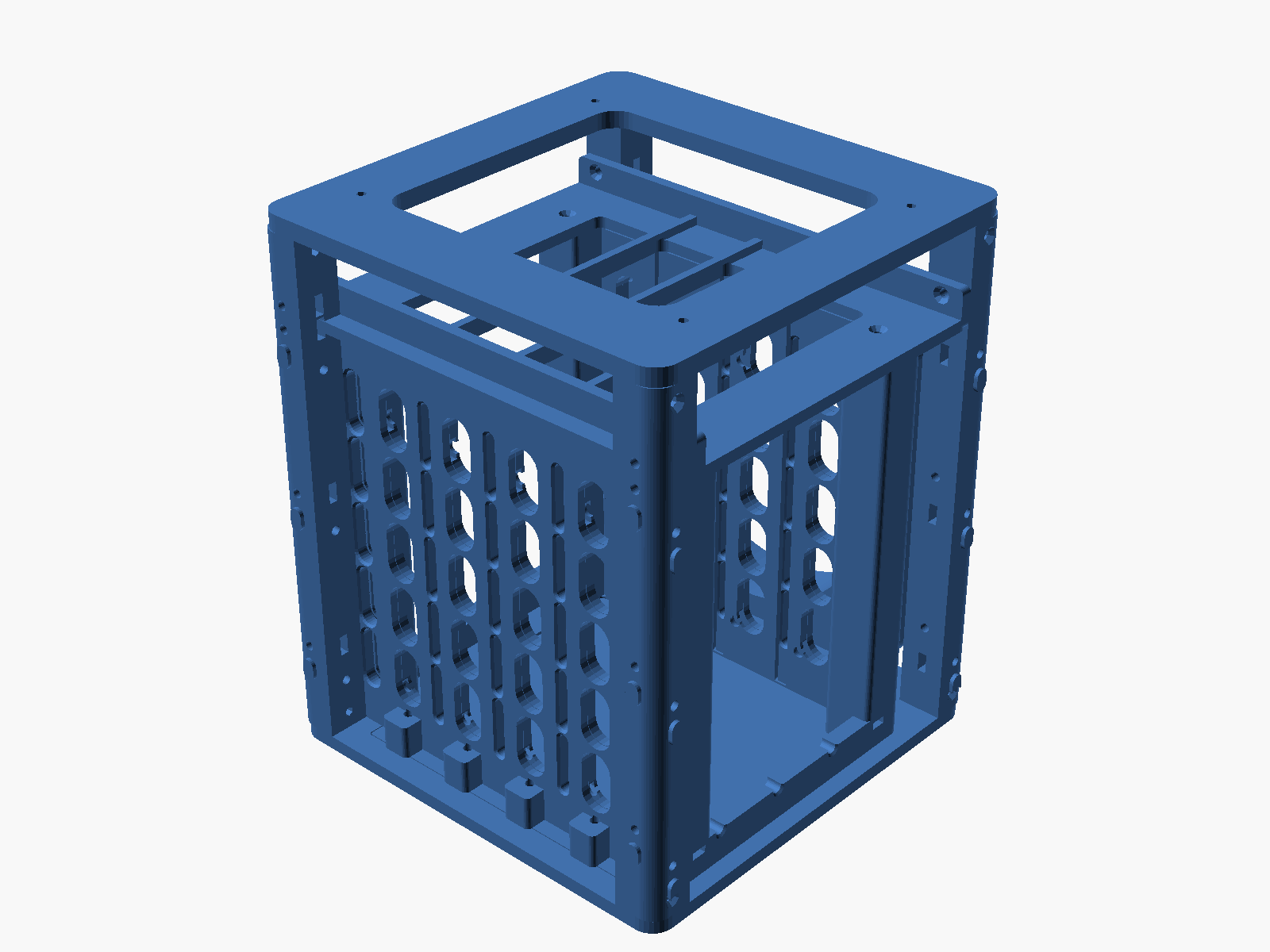
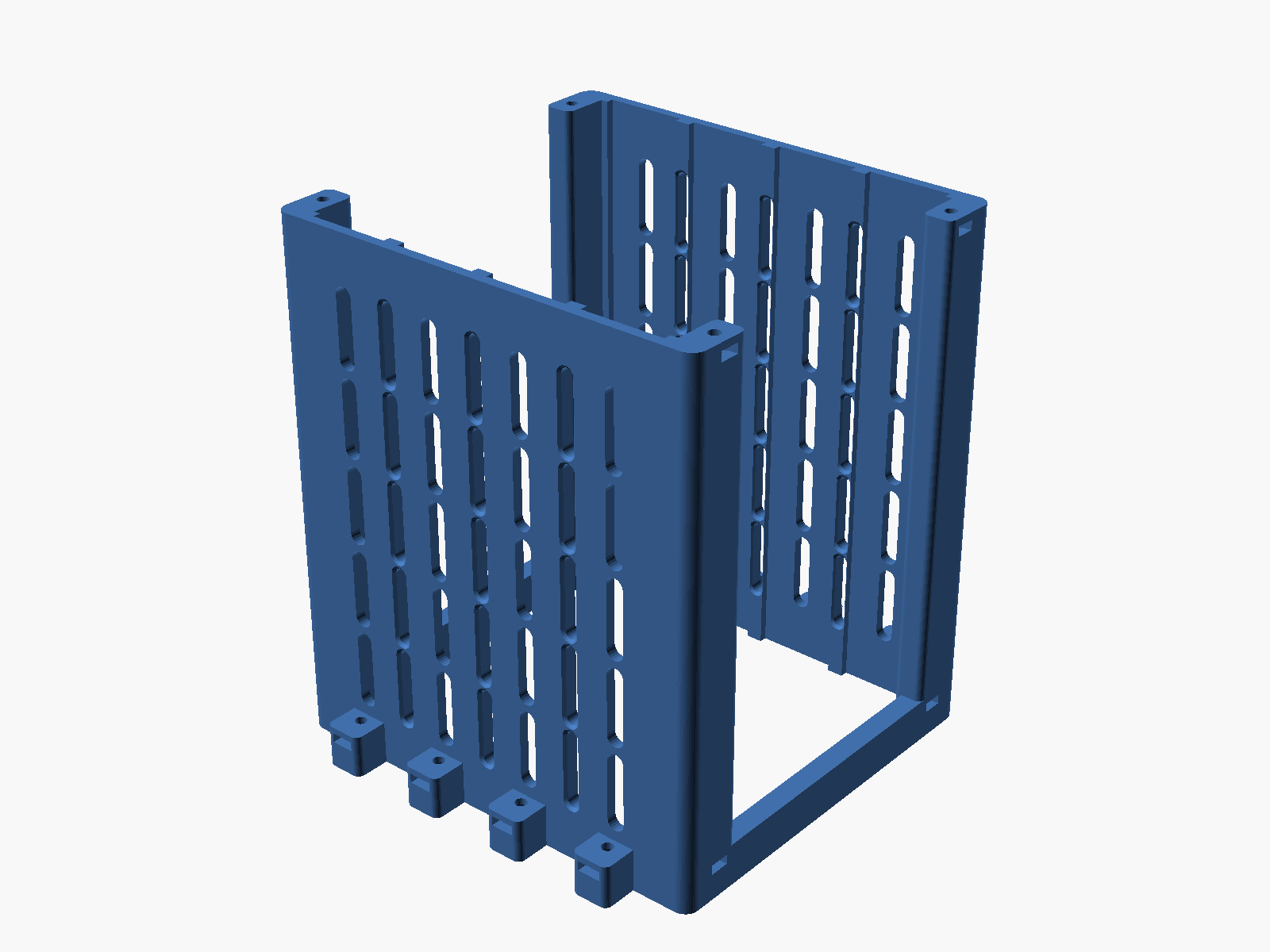
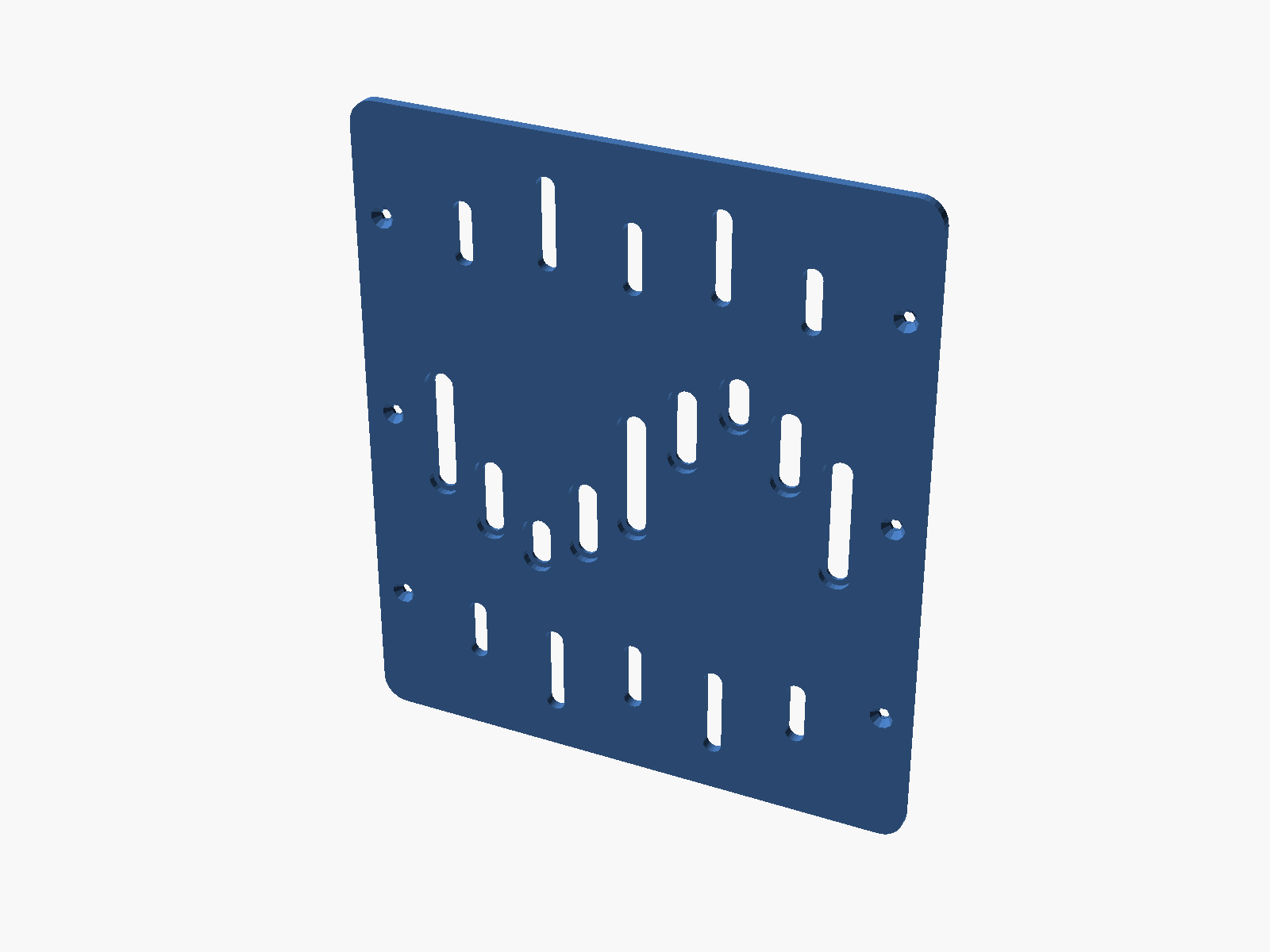
The main project is a custom NAS enclosure built around a fanless mini PC. It’s a single OpenSCAD codebase where config/ is the single source of truth: shell dimensions, drive geometry, print clearances, and hardware choices all live in shared parameter files that every part imports.
The parametric approach shows up in the details. Drive spacing is one knob — the config literally says “keep this as the single pitch knob” next to hddBackplanePitch = 29, matched to the backplane’s 29 mm drive spacing — and the bank width, slot gaps, and cage geometry all derive from it. The mini PC pocket is defined by measured body dimensions plus an explicit clearance parameter, so swapping the target machine is a config edit, not a redesign.
Iterating in millimeters
Because the parts are code, the design history is a commit log, and it reads exactly like tuning software in production. A few real entries:
tweak: shroud height 39mm (1mm fin clearance, not 1.5)— followed shortly byshroud height back to 38.5mm (1.5mm fin clearance). Printed it, checked it, reverted the guess.fix: size magnet pockets to the Ø6x2 magnet, not deeperfeat: 45-degree beveled top lip on front/back panels for printability— geometry changed specifically so the printer can bridge it without support.
Where a dimension is genuinely uncertain — captive nut pockets, drive slot fit, screw lengths — I don’t guess and reprint the whole part. The repo has dedicated test coupons: small nut-slot tuning coupons, drive-rail fit previews, and screw-length validation parts that print in minutes and settle the tolerance question before it’s baked into a six-hour print.
One codebase, four enclosures
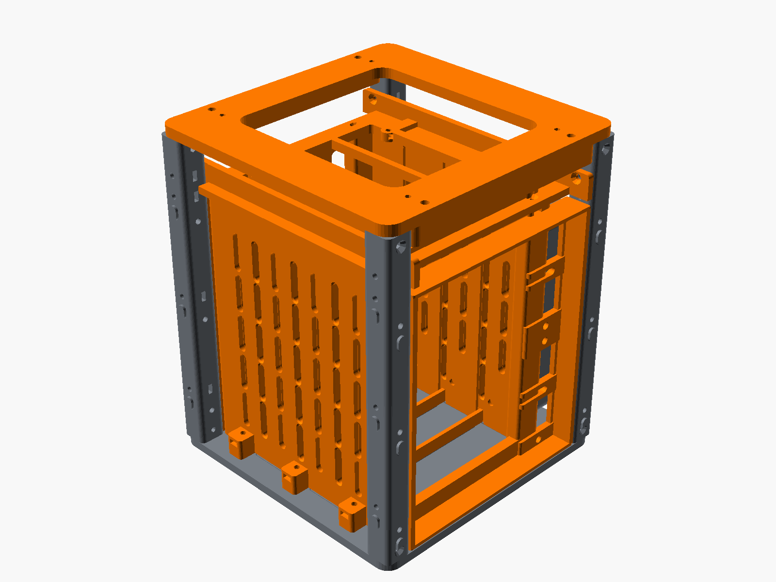
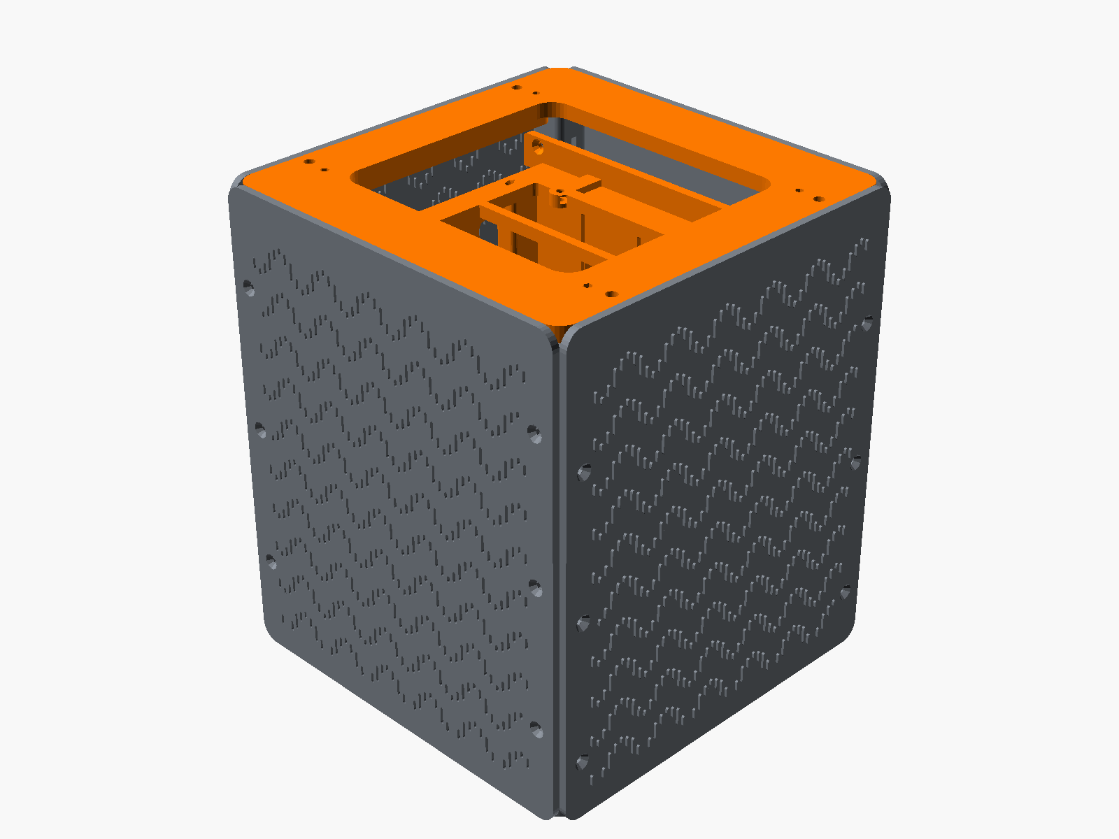
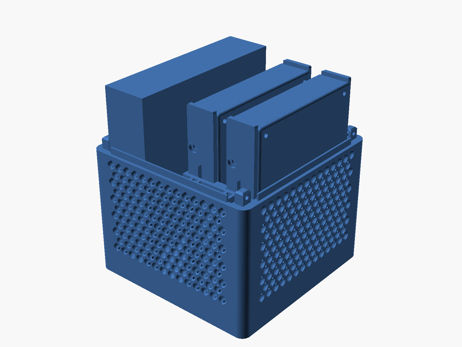
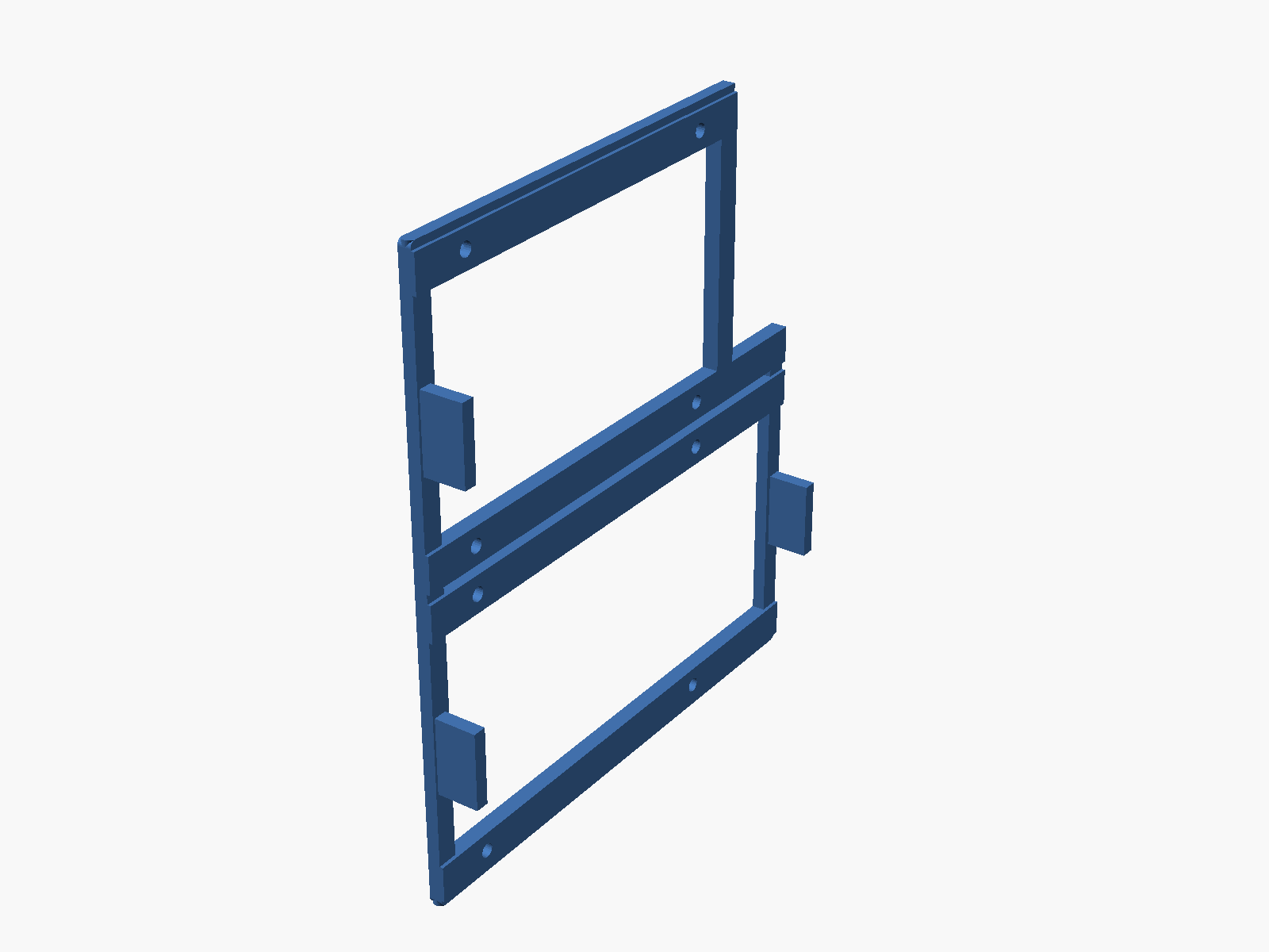
The concepts you can spin below — the four-bay cube, the two-bay upright, the wide variant, an eight-bay rack version — aren’t separate designs. They’re different entrypoint files over the same shared modules and config, the way one component library ships multiple products. The rackstack frame builds on an open-source rack system I’ve extended with my own catalog of trays and carriers for the mini PCs I actually run.
The viewers themselves are part of the same toolchain: a just build renders every part and preview STL, and my own stl-viewer-cli serves them — it’s also what’s rendering the interactive models on this page.
It all runs Unraid, the OS I help build — on hardware I designed myself.
Signing the work
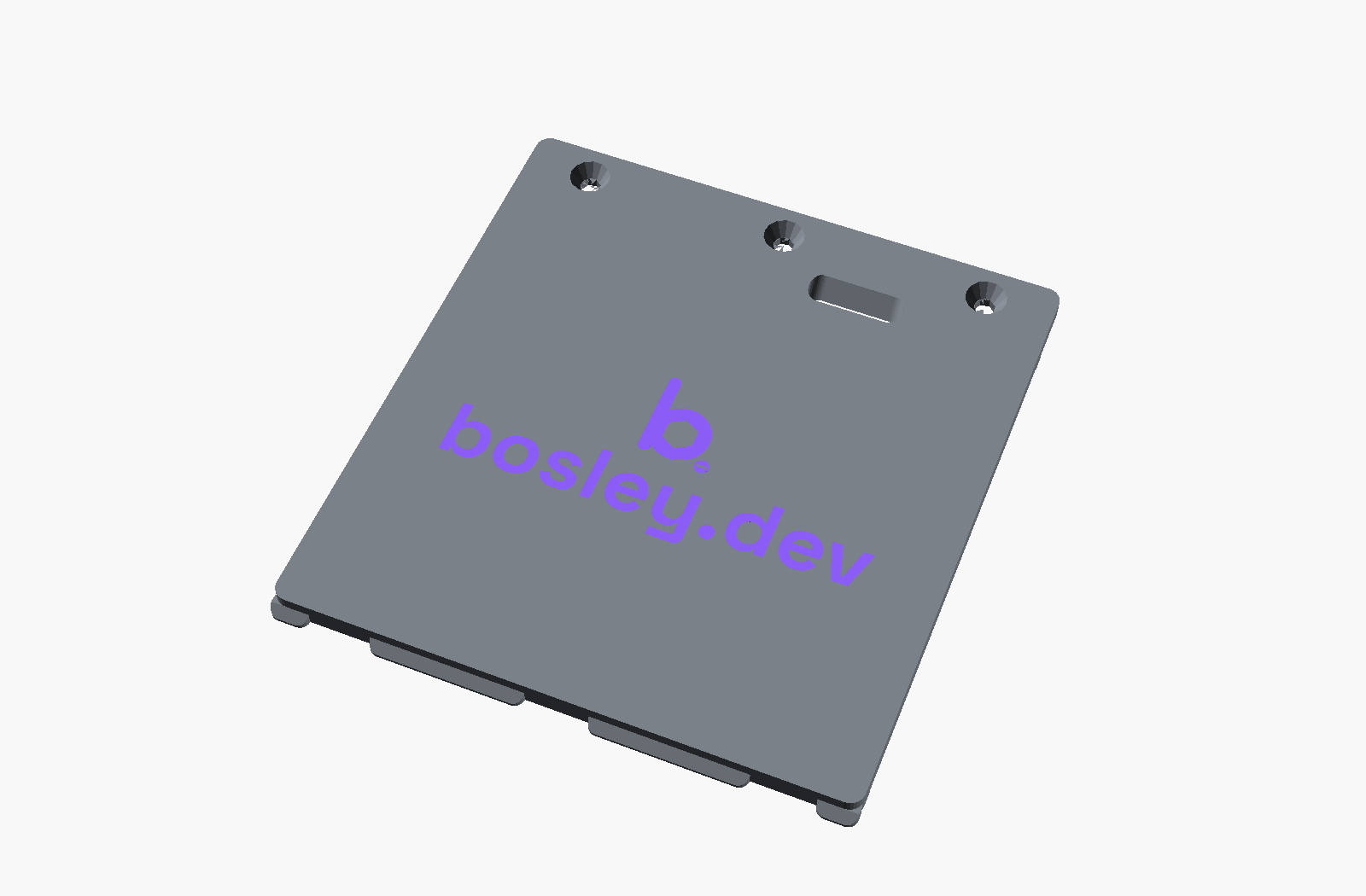
The NAS loads from the bottom, and a single printed plate holds the whole drive stack in. Two details on it come out of the parametric workflow: a maker’s mark and a way to get the plate back out.
The mark is my bosley.dev logo — the same rounded-hex b this site uses. It lives as a real vector, so it drops into the model as a linear_extrude(import(...)); change the artwork and the plate updates on the next render. It’s a flat two-colour inlay rather than an engraving: the plate carries a shallow recess, and the logo prints as a separate body that fills it flush in a second filament.
The other detail is a finger pull. The plate seats flush in its pocket, so a notch on the rear edge would be buried against the pocket wall. Instead there’s an angled slot in the flat of the underside — tilted so its walls stay printable, with a lip you can catch with a fingernail or a flat screwdriver to lever the plate down once the screws are out. The angle came off a strip of test coupons, like the other uncertain dimensions here.
The wrist rest
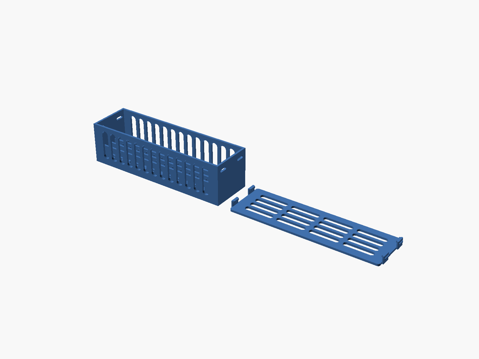
Smallest project here: a modular wrist rest sized to my keyboard, written as one parameterized SCAD file. The board length and module count are parameters — the file computes that an Aula F75 Max needs two modules and sizes each to half the board. Each module is a hollow storage box with a sliding lid, magnet detents that click it shut, and print-in-place coupling magnets in the end faces so any two modules snap together in the right orientation. Change module_count and it re-plans the whole thing.
Why I work this way
Parameterize the real constraints, derive everything else, and make iteration cheap enough that you actually do it. It’s the same loop I use for platform work — calipers and a printer instead of dashboards and deploys: measure, model, test the risky dimension in isolation, ship, revise.
Got a hard problem?
I'd like to hear about it.

Let's talk
If you're wrestling with product strategy, platform architecture, engineering leadership, or making AI actually useful, drop me a line. Worst case, we have a good conversation.